Introduction
A Time Domain Reflectometer (TDR) is a device that is used to locate faults in electric cables. It is based on the principle of reflection of electric signals by faults. A TDR sends a fast rising rectangular pulse down a cable, samples it at the input and processes the sampled signal to determine presence of a fault in the cable. A TDR is also able to determine the type of the fault and its point of occurrence. To read further on time domain reflectometry, check this post . There are commercial TDRs in the market from manufacturers like Tektronix and Megger. These TDRs are, however, expensive (ranging from hundreds to thousands of dollars). At the Centre for Data Science and Artificial Intelligence (DSAIL), we have developed a low-cost Raspberry Pi based TDR.
Conceptualisation
From our interactions with rangers from Ol Pejeta Conservancy and Dedan Kimathi University of Technology Wildlife Conservancy , we learnt that their perimeter electric fences are prone to faults. To detect these faults, they have to do periodic monitoring of the fences. Once they detect a fault, they walk along the fence with a voltmeter measuring the voltage of the fence. The voltage is expected to dip at the sections of the fence beyond the fault.
This method of fault detection and localisation is inefficient. Firstly, a person is required to do periodic monitoring of the fence. This means the fault detection process may not be timely. Secondly, the localisation procedure that involves walking along the fence is laborious and time consuming given the long cables that are used to create the fences. The Dedan Kimathi University of Technology Conservancy, for example, with an area of 126 acres has a 4.8 km long perimeter fence. Larger Protected Areas (PAs) have fences that span to hundreds of kilometres.
At DSAIL, we set out to look for a solution to help the rangers solve the problem of fault detection and localisation in electric fences. While working with a friend from Telkom Kenya, well technically I was not working but 'hitchhiking' since he travels to different parts of the country. So, from these trips I learnt that they use a device called an Optical Time Domain Reflectometer (OTDR) to detect and localise faults in fibre optic cables. An OTDR sends an optical pulse down a fibre optic cable and analyses the reflected pulse to detect and localise faults. This sparked an interest in me and I thought that I should see if this concept can be used to detect and localise faults in electric fences. From my research, I came across the concept of time domain reflectometry in electric cables.
From my observations, I realised that the existing time domain reflectometry technologies are expensive. They also required the presence of a person to be operated. This makes them unsuitable to use with electric fences. To help solve this problem, I started looking for ways to develop a low-cost TDR that can be easily interfaced with the fence. The goal was to develop a TDR based on a low-cost microcontroller, a Single Board Computer (SBC) or a Field Programmable Gate Array (FPGA). The microcontrollers were not fast enough for this task and the FPGAs were expensive so I decided to explore the SBCs.
A basic TDR comprises a fast-rising pulse generator, a fast-sampling Analogue to Digital Converter (ADC) and a processing unit. Figure 1 shows a block diagram of a TDR.
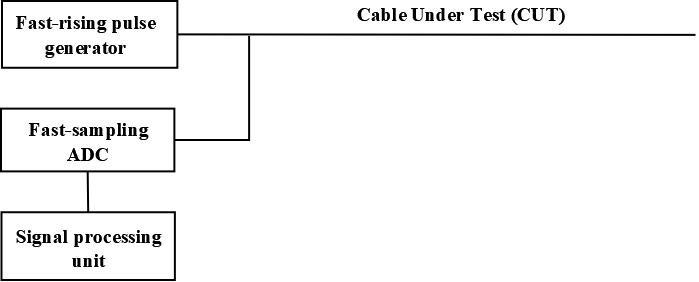
Figure 1: Block diagram of a TDR system.
The bottleneck in this task was on the fast-sampling ADC part. Electric signals in conductors travel at a speed close to that of light in vacuum ( 3 × 10⁸ m · s-1). The data acquisition rate needs to be of order Mega Samples Per Second (MSPS) and above. Surprisingly, I came across a project on ultrafast data acquisition using the Raspberry Pi. The project employed Secondary Memory Interface (SMI) and Direct Memory Access (DMA) [1].
SMI is a parallel interface found in all Raspberry Pi versions. It enables one to interface the Raspberry Pi with peripheral devices using a parallel interface. This way, it is possible to grab all data bits from a peripheral device using a single clock cycle. SMI (parallel) interface is faster compared to serial interfaces such as Serial Peripheral Interface (SPI), serial Universal Asynchronous Receiver-Transmitter (UART) and Inter-Integrated Circuit (I2C) [2]. Serial interfaces require multiple clock cycles to transfer one data sample. The AD9226 ADC was used for the data acquisition. The AD9226 is a cheap ultrafast (65 MSPS) ADC that has a parallel interface and, hence, can be interfaced with the Raspberry Pi using SMI [1].
To transfer the data to memory, DMA was used. DMA is a method of moving data around a computer at high speeds. DMA operates independent of the Central Processing Unit (CPU). The CPU is prone to jitter due to interruption by high priority tasks. However, our data acquisition requirement is time sensitive and so DMA was the best way of moving data from the ADC to the memory. The CPU is only used to initialise the data transfer and then the DMA takes over the process. Once the process is over, the DMA reports to the CPU that the process is over [3]. When transferring data from or to a flash drive for example, your computer uses DMA too.
Using the AD9226 and a Raspberry Pi 4, a sampling rate of 31 MSPS has been achieved. This is sufficient data acquisition rate for a TDR. A 74AC14 Schmitt trigger is used to generate fast-rising pulses at 8.3 kHz. The Pulses are applied to a cable and sampled at the input port by the ADC. The Raspberry Pi has been loaded with programs to drive the ADC and to transfer the ADC output to memory for saving. The saved signal samples are then processed to detect faults in electric cables. Figure 2 shows the Raspberry Pi TDR.
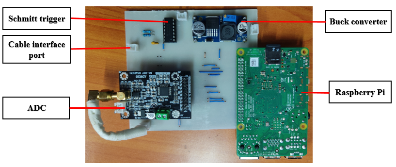
Figure 2: Raspberry Pi based TDR.
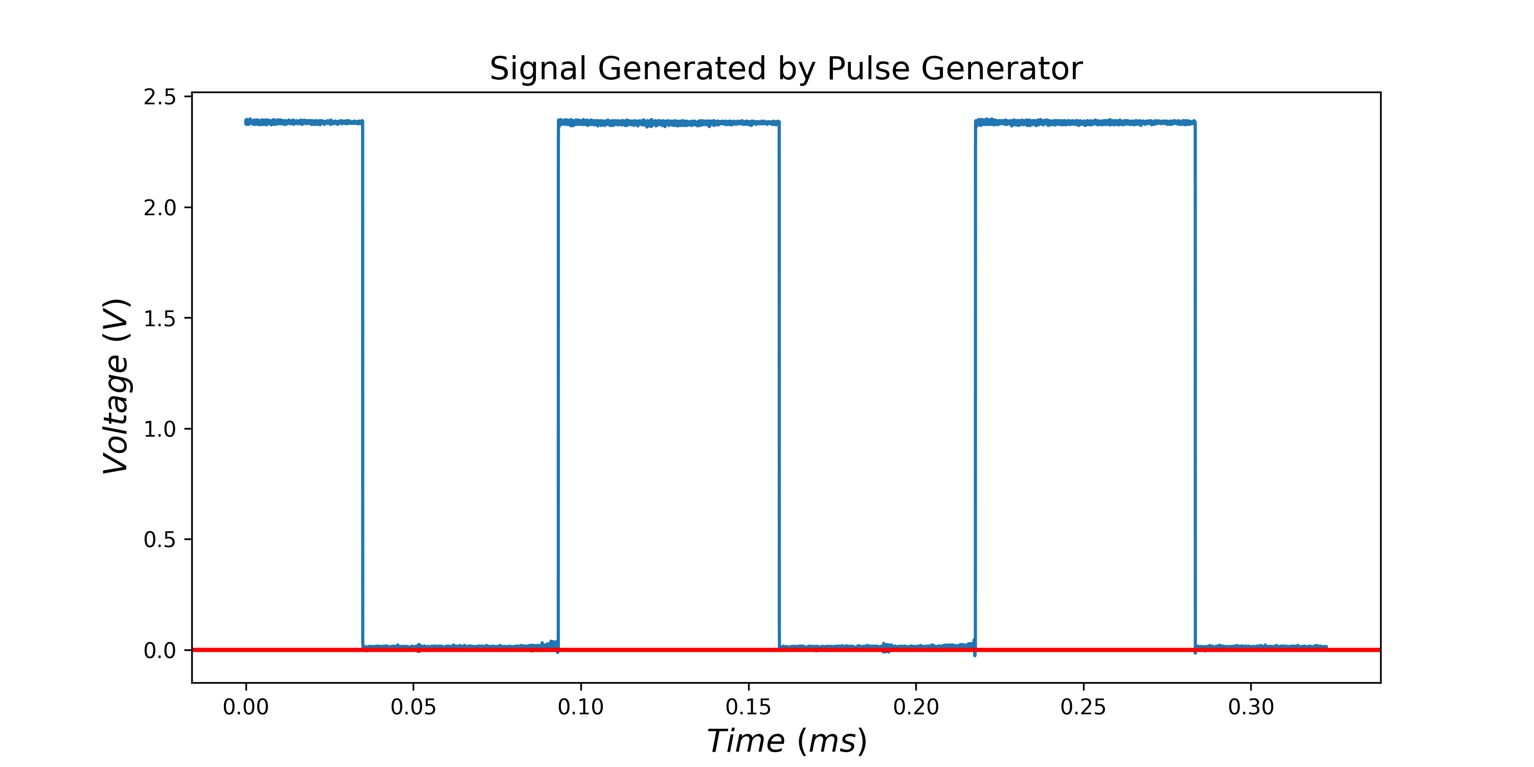
Figure 3: Pulses generated and sampled by the TDR system.
A section of the Dedan Kimathi University of Technology Conservancy electric fence that is 106 m was used to simulate open circuit and short circuit faults. The TDR system was used to apply rectangular pulses to the fence during the simulations, sample the signals at the input and then save them. 435 files were collected from the exercise. The saved signals have been used to develop a time domain reflectometry algorithm for fault detection and localisation. The algorithm is able to detect a fault with a precision of ± 1.18 m.
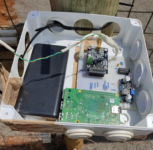
Figure 4: TDR system during a data collection exercise.
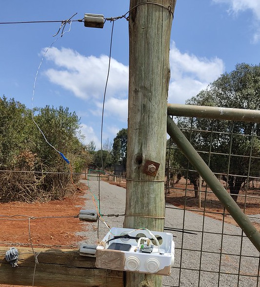
Figure 5: TDR system connected to the fence.
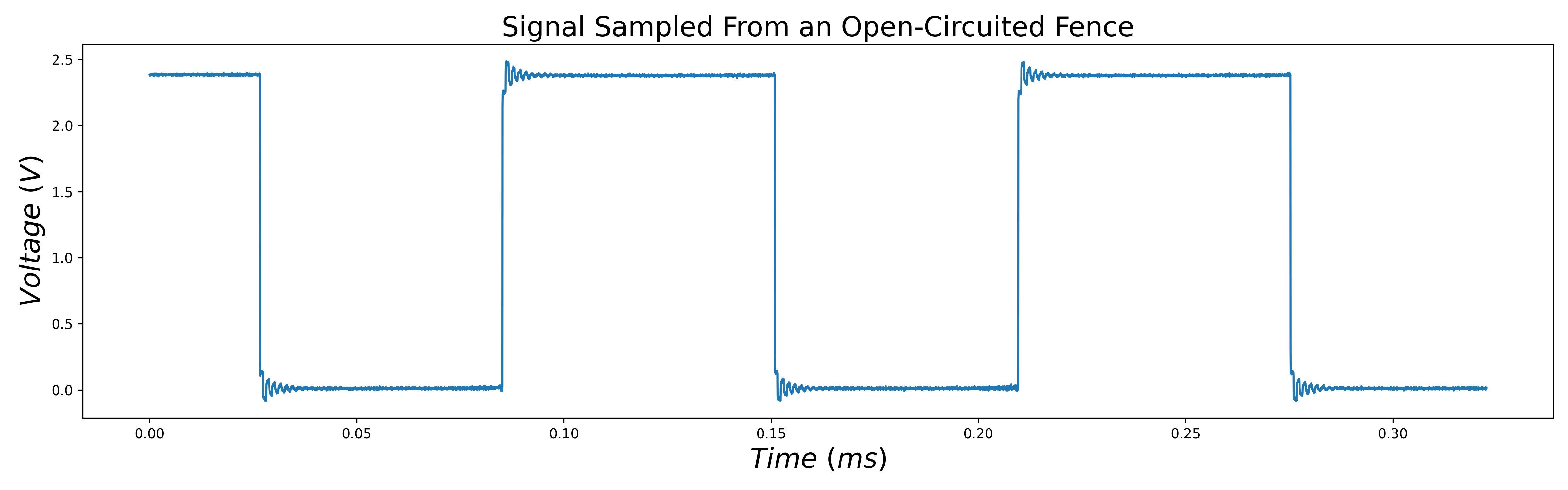
Figure 6: Signal sampled from an open-circuited fence.
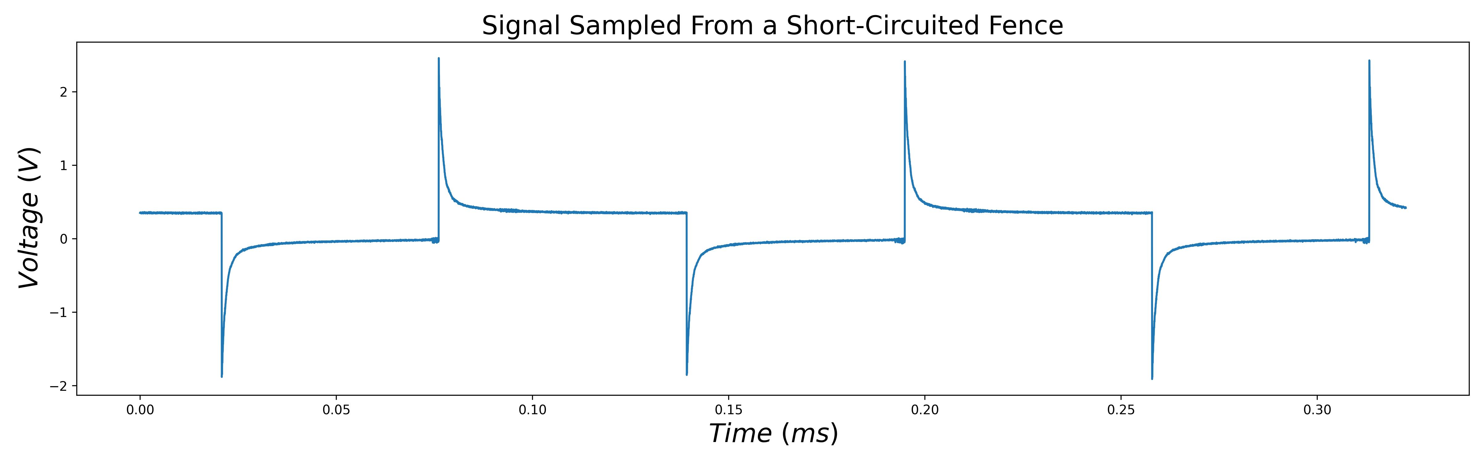
Figure 7: Signal sampled from a short-circuited fence.
References
[1] J. P. Bentham, "Raspberry Pi Secondary Memory Interface (SMI)", Lean2, 16 July 2020. [Online]. Available: https://iosoft.blog/2020/07/16/raspberry-pi-smi/. [Accessed 1 December 2022].
[2] J. P. Bentham, "Fast data capture with the Raspberry Pi", Lean2, 11 June 2020. [Online]. Available: https://iosoft.blog/2020/06/11/fast-data-capture-raspberry-pi/. [Accessed 1 December 2022].
[3] J. P. Bentham, "Raspberry Pi DMA programming in C", Lean2, 25 May 2020. [Online]. Available: https://iosoft.blog/2020/05/25/raspberry-pi-dma-programming/. [Accessed 1 December 2022].