Computers, processors & microcontrollers
- Operating system: a manager of resources provided by the underlying architecture.
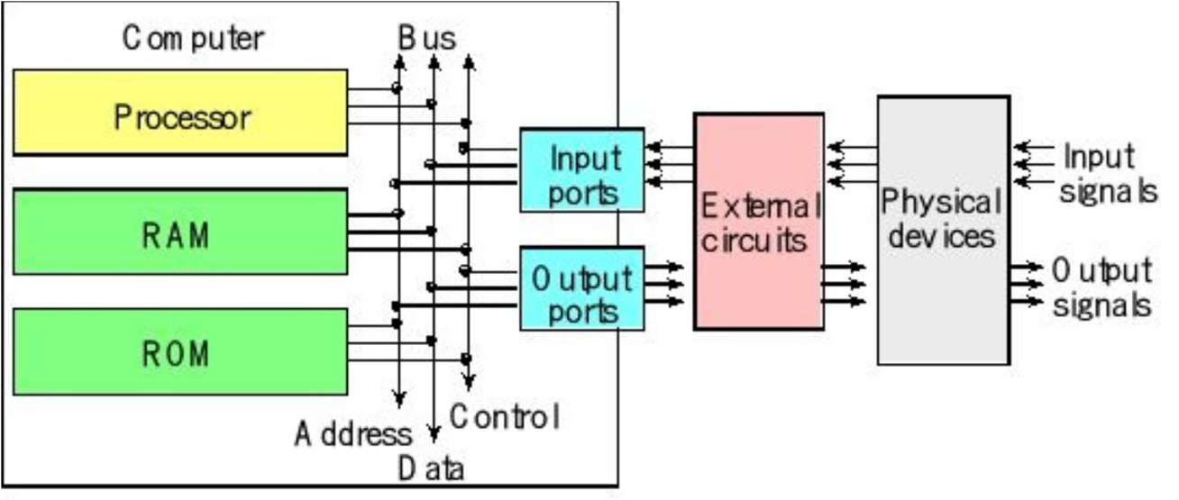
- A computer: combines a central processing unit (CPU), random access memory (RAM), read-only memory (ROM), and input/output (I/O) ports.
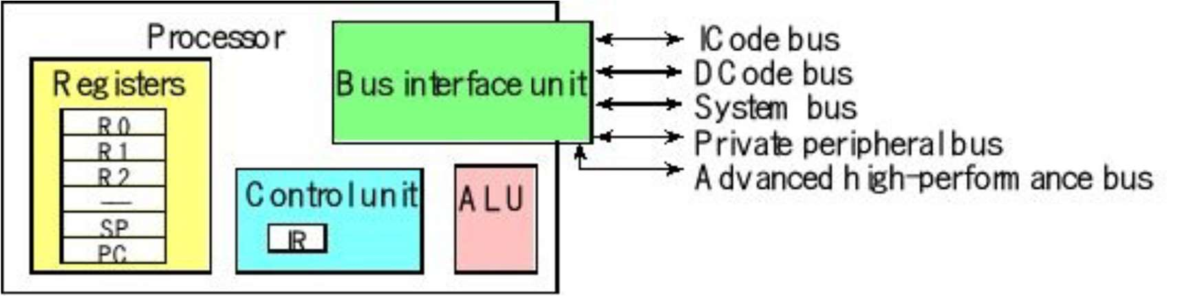
- A processor: often called the Central Processing Unit (CPU) — the primary component of a computer that performs most of the data processing and calculations. It acts as the "brain" of the system, responsible for fetching, decoding, and executing instructions.
- A microcontroller: contains all the components of a computer (processor, memory, I/O) on a single chip. Microcontrollers are designed for embedded applications.
Introduction to embedded systems
- Embed: to incorporate or integrate something into a larger system.
- Embedded system: a computational system based on the integration of both software and hardware, built to perform specific tasks.
There are two classifications of embedded systems:
- Transformative: collects data from inputs, makes decisions, and affects its environment by driving actuators.
- Reactive: collects data in a continuous fashion.
Embedded systems make use of specialized ICs called microcontrollers, which bundle features to simplify monitoring and control (an MCU = CPU + peripherals + support circuits + memory).

Example: a microcontroller inside a washing machine controls wash cycles; in a fridge, it monitors temperature. At DSAIL, water level monitoring sensors track water level changes along rivers.
Operations of an embedded system
- Closed loop control: controlling an output variable based on one or more input measurements — for example, adjusting temperature or changing direction.
- Sequencing: controlling an output through a sequence of steps.
- Signal conditioning and processing: averaging together sensor readings, conditioning signals, filtering out noise.
- Communication and processing: interacting with other systems and subsystems.
Camera trap
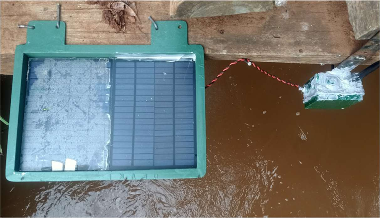
Water level sensor
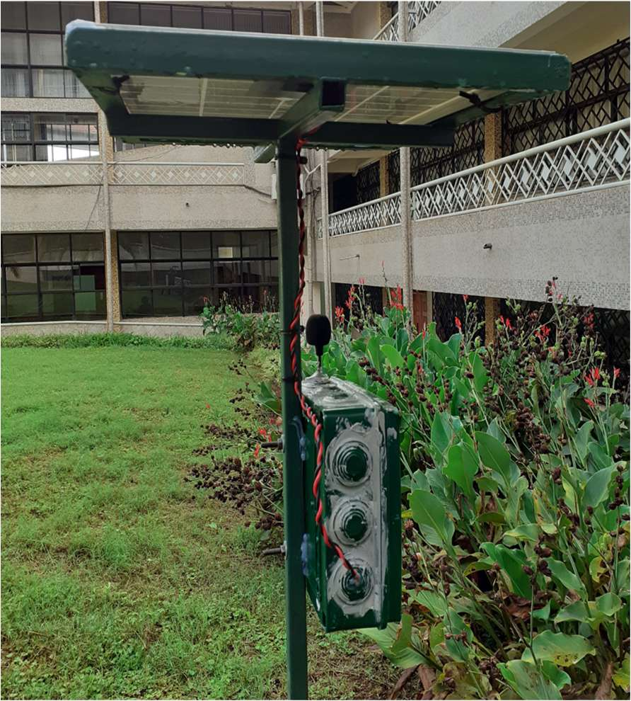
Acoustics sensor

Attributes of an embedded system
- Interfacing with inputs and outputs: embedded computers need to sense the environment and issue control commands in response (analog, digital, ADC, DAC).
- Specialized peripheral hardware circuits: signals often must be processed before conversion to the digital domain for the CPU — amplification, scaling down signals, filtering noise.
- Concurrency: embedded controllers must manage multiple activities concurrently, often with precise control of timing.
- Responsiveness: providing enough responsiveness by sharing the CPU's
time across many activities.
- The processor must be fast enough to complete critical processing before its deadline; developers should optimize code to do necessary work with very few instructions.
- The processor needs to stay focused on critical processing.
- Processing and communication should be split.
- Reliability and fault handling: embedded systems are expected to work correctly and reliably — unlike normal computers, the user cannot simply reboot them. The impact of failure should be minimized.
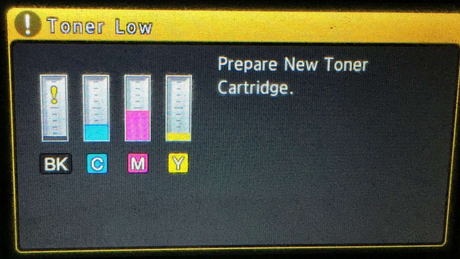
- Diagnostics: it should be easy to find and repair a faulty component quickly. Hard-coded diagnostics support is common in printers, scanners, and fridges.
- Constraints: embedded systems must not be too large, expensive, or heavy.
Embedded system essential: digital data transmission
Digital data transmission is the transfer of data between two or more digital devices, in the form of bits, over channels such as fiber optic, conductor, or wireless links. It can be either parallel or serial.
- Multiple data bits are sent at the same time over multiple channels.
- Data reaches the receiver in one go.
- More channels.
- Very expensive.
- Data bits are sent through a single channel, one after the other.
- One communication channel.
- Less expensive.
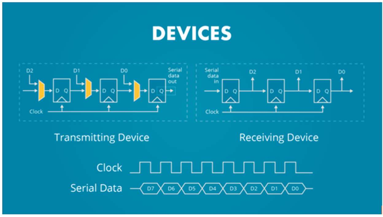
- Uses shift registers — a digital conveyor belt with memory cells called flip-flops.
- A clock signal controls everything.
- With every clock pulse, the binary value inside the register moves one step, bit after bit, until the whole digital word has moved through.
- Can include a start bit and a stop bit.
Serial communication
Serial communication falls into two main categories:
- Synchronous — a clock signal is needed.
- Asynchronous — a clock signal is not needed.
Under synchronous communication, one common method is:
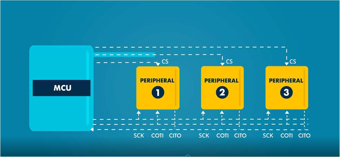
SPI (Serial Peripheral Interface)
- Involves two ICs / shift registers working together: the controller/master and the target/slave.
- Movement of bits is bidirectional — half duplex.
- The controller is more powerful, since it controls the clock and the chip select.
- Common pins: MOSI/COTI, MISO/CITO, SCK, CS.
- Demerits: no data acknowledgement once sent, no per-target addressing (a chip-select line is needed for every target), and no error-checking mechanism.
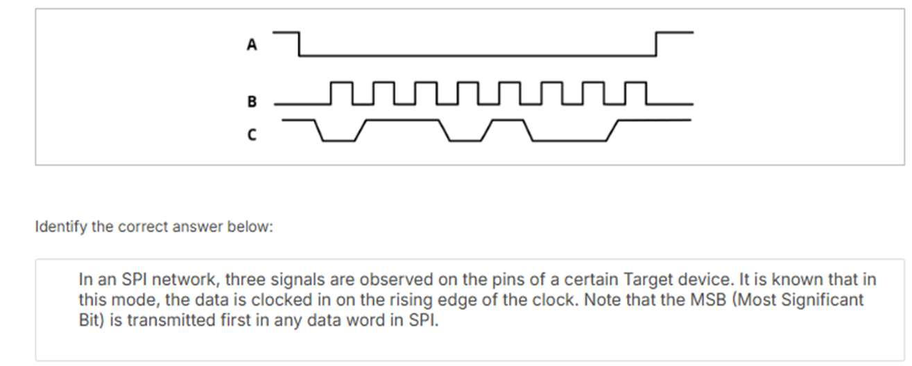
In an SPI network, three signals are observed on the pins of a certain target device. It is known that in this mode, the data is clocked in on the rising edge of the clock. Note that the MSB (Most Significant Bit) is transmitted first in any data word in SPI. Identify the correct answer.
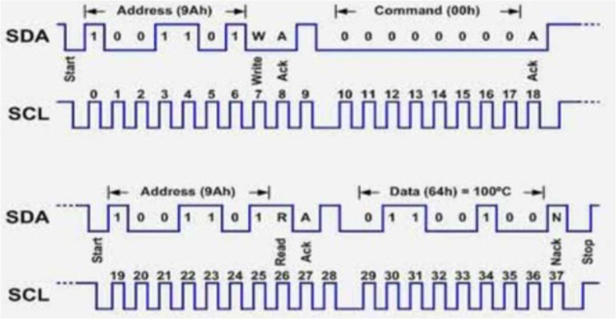
I2C — Inter-Integrated Circuit
A protocol widely used in serial communication, introduced by Philips Semiconductors in 1982.
- Two-wire communication (SDA — Serial Data, SCL — Serial Clock).
- Half duplex — can transmit in two directions, but not simultaneously.
- Addressing: each target is identified with a unique 7-bit or 10-bit address.
- Error handling includes NACK/ACK bits to confirm successful data transmission.
Steps
- Start: the master initiates communication by pulling the SDA line low while SCL remains high.
- Addressing: the master sends the 7-bit address of the target slave, followed by a read/write bit.
- Acknowledgement: the addressed slave responds by pulling SDA low during the next clock pulse.
- Data transfer: data is sent in 8-bit frames, each followed by an ACK/NACK bit.
- Stop condition: the master ends communication by releasing SDA to high while SCL is high.
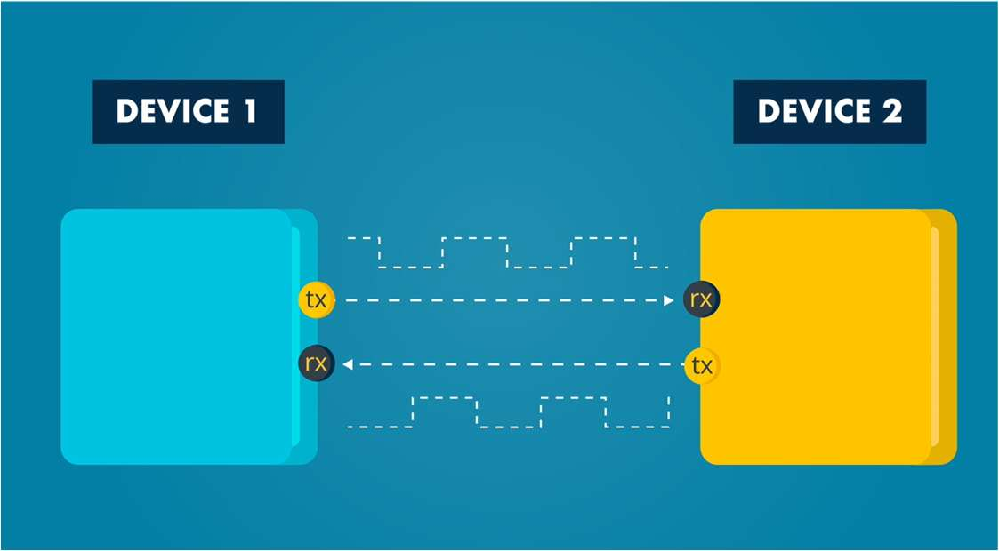
UART (Universal Asynchronous Receiver/Transmitter)
Under asynchronous communication, the common method is UART:
- No clock.
- Data transmission rate — the baud rate — is measured in bits per second.
- The baud rate is prearranged between the transmitter and the receiver.
- Common connections: TX and RX.
- Some UARTs can be configured as synchronous: USART (Universal Synchronous/Asynchronous Receiver/Transmitter).
- Framing bits are required at the beginning and end of the data.
- Data transmission usually follows one of two patterns: 8-bit transmission, or 8-bit transmission plus a parity bit.
- Parity pattern: an error-checking mechanism that helps ensure data is correctly received.
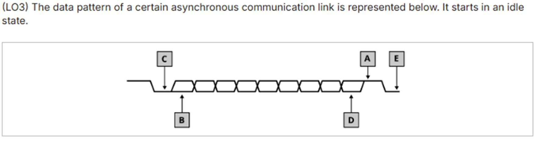
The data pattern of a certain asynchronous communication link is represented in the diagram above, starting in an idle state. Identify what each of the labelled points (A through E) represents.
Analog communication (AnalogIn)
With the ADC, a continuous analog wave is sampled and converted to a digital number. Below is the master pipeline for an analog sensor:
1. Physical event (e.g. heat) drives an analog sensor, producing a continuous analog signal.
2. The ADC peripheral samples the wave and turns it into a binary number — a parallel digital byte (e.g. 10110011).
3. A TX shift register flattens the byte into a single-file line of bits — a serial channel, one wire, bit by bit.
4. An RX shift register rebuilds the single-file bits back into a parallel digital byte (10110011).
5. The byte lands in CPU memory, via an interrupt-driven or Direct Memory Access approach.
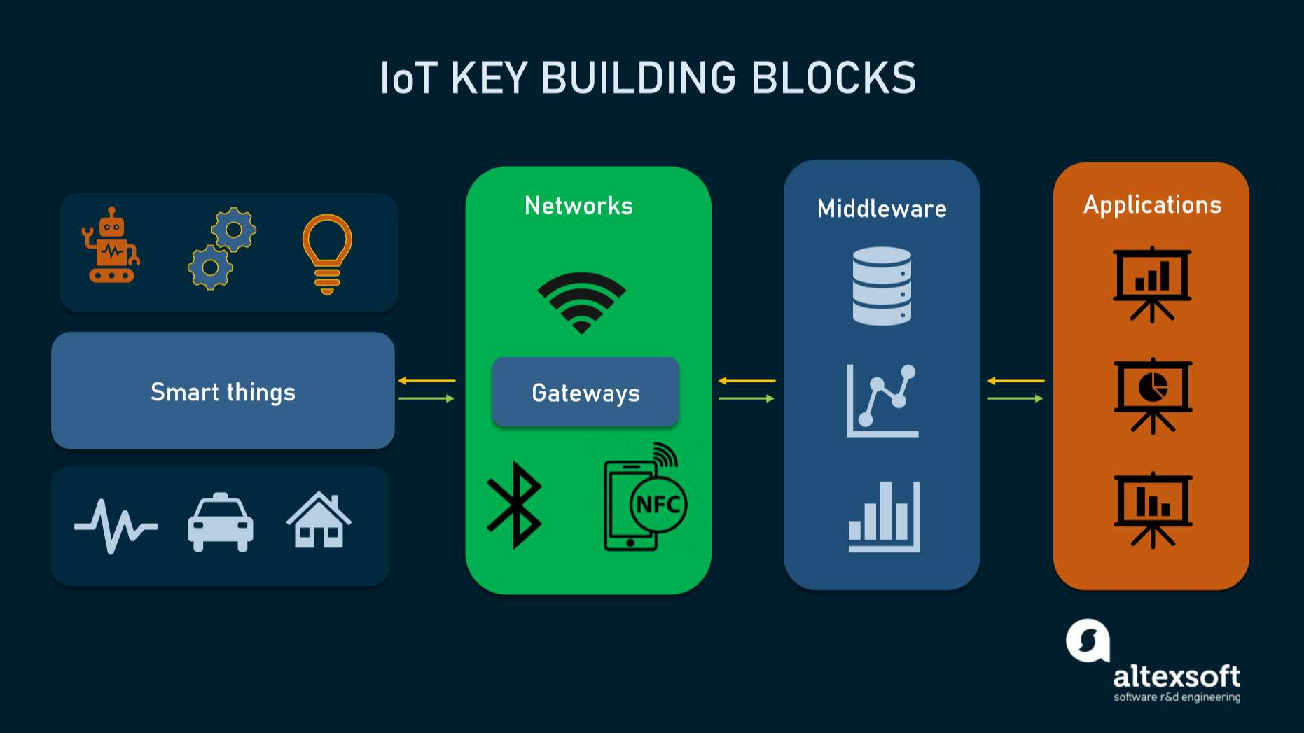
Embedded systems — Internet of Things connection
- Embedded systems are the backbone of IoT.
- An IoT device is an embedded system connected to the internet.
Connectivity: wireless sensor networks
Low-power wireless protocols are designed to transmit data using very little energy, allowing IoT devices to last a long time on constrained power sources like batteries. The two strengths of these protocols are low power and self configuration.
Categories
- Short range protocols: BLE (Bluetooth Low Energy).
- Medium range protocols: Zigbee.
- Long range protocols: unlicensed — LoRaWAN, Sigfox; licensed — NB-IoT, LTE.
Let's focus on LoRaWAN.
LoRaWAN
- LoRa: a physical radio communication technique based on CSS technology, developed by Semtech, a producer of analog and mixed-signal semiconductors. LoRa is used for sending small amounts of data over long distances — the record stands at 960 miles — making it well suited for IoT.
- LoRaWAN: a Media Access Control (MAC) layer protocol built on top of LoRa modulation. It's the software layer that defines how to use the LoRa hardware.
- LoRaWAN is developed and maintained by the LoRa Alliance, based in Fremont, California — a non-profit technology ecosystem of which Semtech is a founding member.
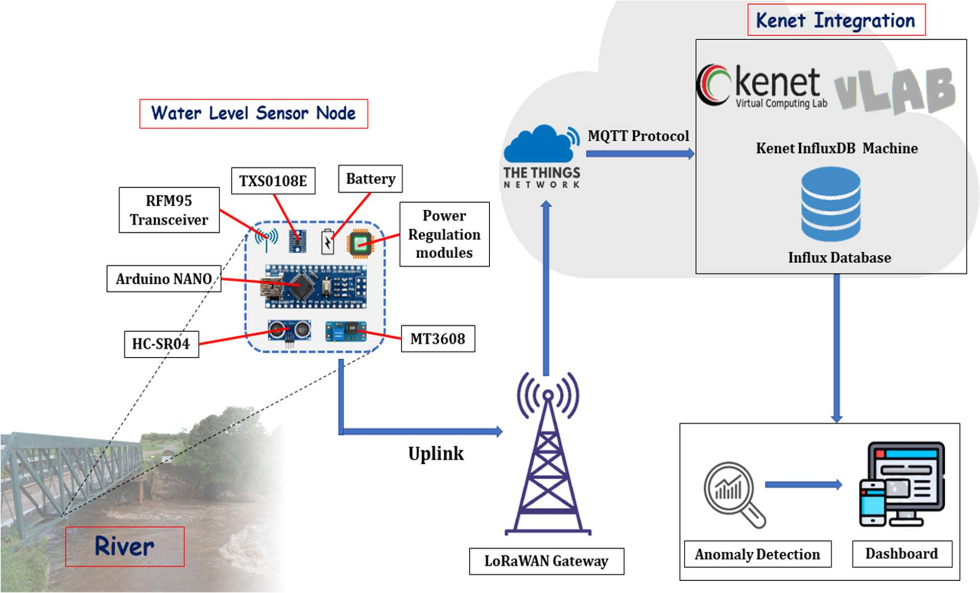
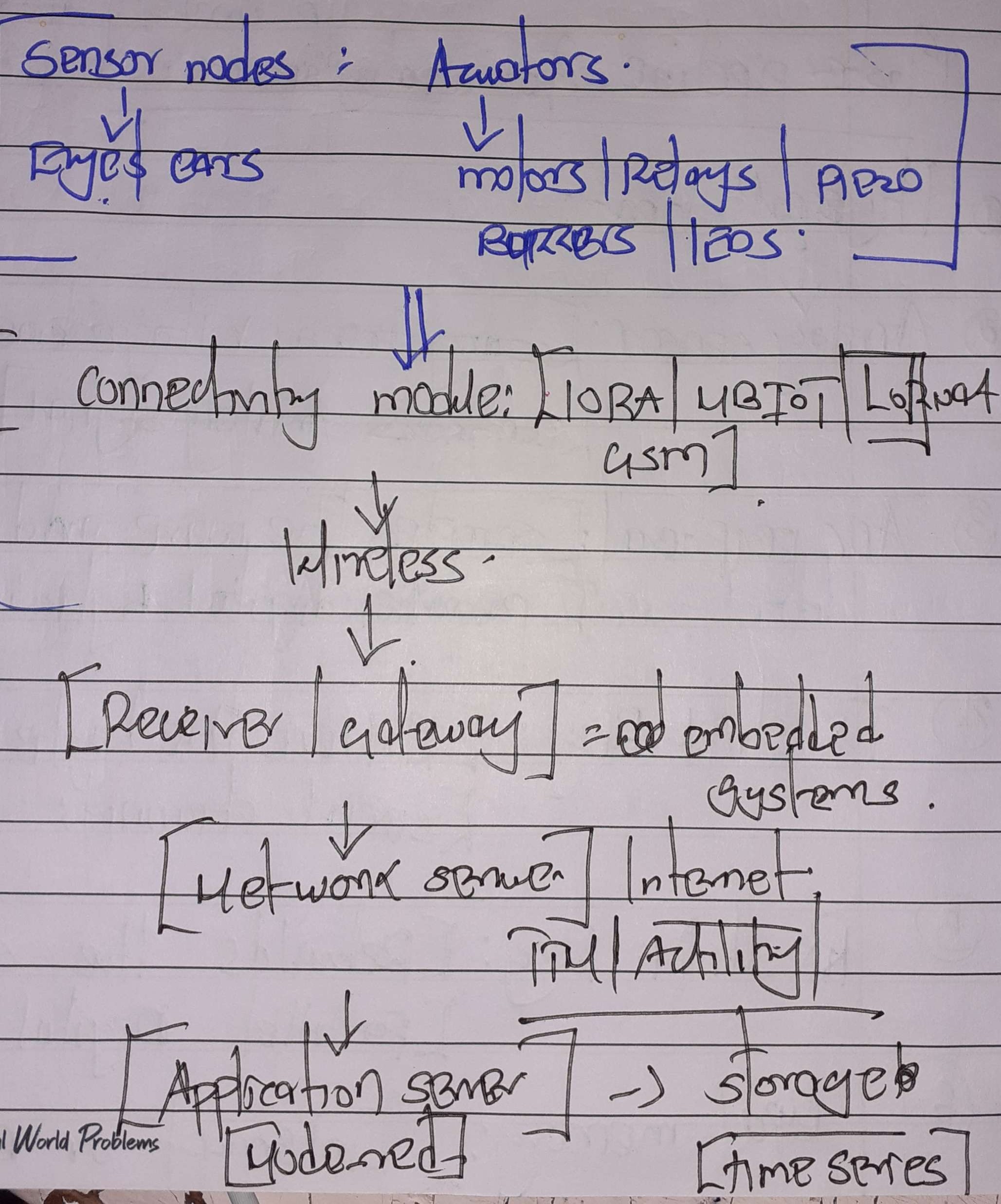
Setting up a LoRaWAN network — what's needed
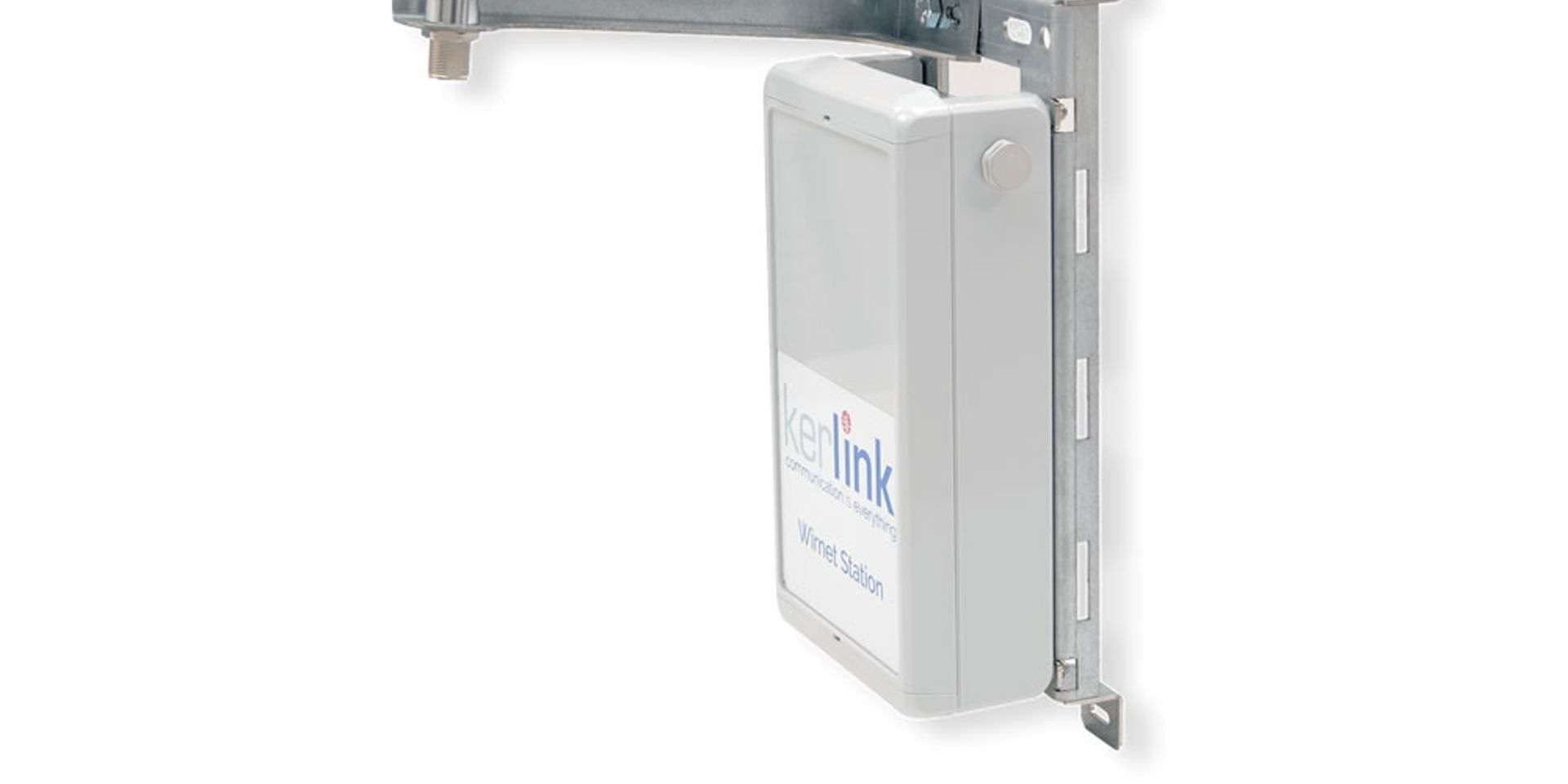
- A LoRaWAN gateway (e.g. Kerlink, The Things Industries, MultiTech).
- Internet access for the gateway (LTE, ethernet, or Wi-Fi).
- Power supply for the gateway.
- A sensor node.
- A network server (e.g. Actility, The Things Network).
- A cloud service to store the data and run visualization tools.
LoRaWAN gateway
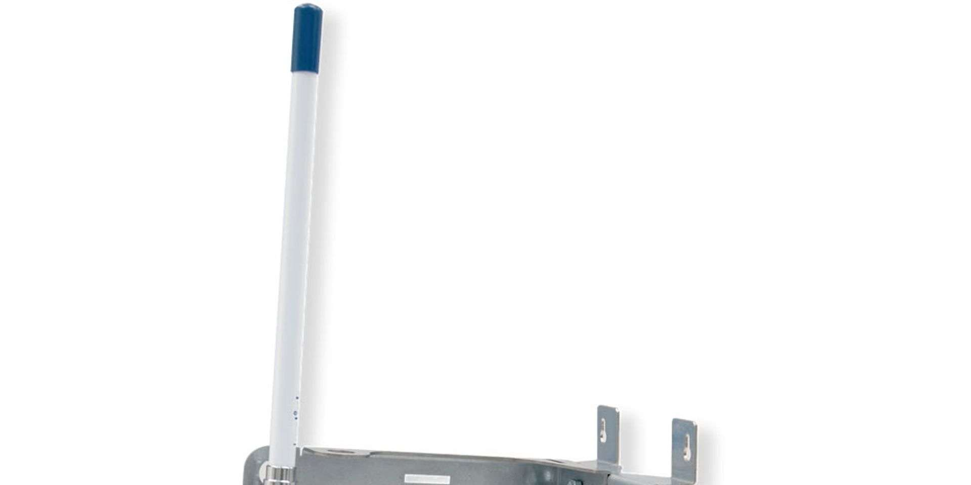
Wall-mounted gateway & antenna
Practical
Introduction to Realtime Operating Systems (RTOS)
- RTOS: an operating system designed specifically to process data and respond to events within a strict, predictable time limit.
Difference from standard operating systems:
- Normal operating systems prioritize smooth user experience and high throughput.
- In an RTOS, the correctness of a program depends not just on what it calculates, but when it delivers the results.
There are two types of RTOS:
Missing a single deadline results in total system failure. Deadline is absolute (e.g. pacemakers).
Meeting deadlines is the goal, but missing one occasionally is acceptable; the system won't crash (e.g. a video streaming app might drop a frame).
Features of RTOS
- Preemptive Priority-Based Scheduling — high priority tasks run first, no matter what.
- Task switching (low latency) — an RTOS is designed to switch between tasks very quickly.
- Inter-Task Communication and Synchronization — because tasks need to
hand off data and work together smoothly without delaying each other, an RTOS provides
highly efficient built-in tools.
- A Mutex is a locking mechanism used to synchronize access to a single shared resource (like a hardware peripheral, a variable, or a memory buffer).
- A Semaphore is a signaling mechanism. It uses a counter to manage access to resources or to synchronize tasks.
- Small footprint — mostly used in embedded systems (microcontrollers), RTOSes are typically very lightweight (a few kilobytes).
ARM MbedOS
- July 2026 is the official End-of-Life (EOL) target for the Mbed platform and OS.
- The Mbed project officially started as an internal research and development initiative inside Arm back in 2005.
- September 2009: the official public launch of the Mbed platform (originally called Mbed 2, which relied heavily on the online cloud compiler).
- 2014–2015: Arm rebranded and expanded it into Mbed OS, transforming it from a simple set of libraries into a full, open-source real-time operating system (RTOS) focused on IoT devices.