Tutorial 1: Sensor Node Components
Introduction
As stated in the introduction, the tutorial will focus on some of the sections in Project Muringato. The main event is the interaction with a replica of the sensor nodes used in data collection. The replicated design is the Arduino Nano based design. The other tutorial sections are:
- Inclusion of the wireless sensor network component and the network server component to enable data transmission. One gateway will be needed and it will be provided during the tutorial session.
- A highlight of how to store the sensor data in a permanent time series database on the KENET servers.
- A highlight of how machine learning can be used in anomaly detection in time series data.
Interaction with the Sensor Node Designs
On the desks, you have been provided with designs of the sensor node used to collect data in Project Muringato. The sensor node layout is an Arduino Nano based water level monitoring device. The designs are provided on two different platforms:
- A breadboard
- An etched circuit board
This is done to bring out the steps followed in the development and realization of the sensor node. The presentation is also suitable in explaining the purpose of each of the components. The design on the etched circuit board is fit for deployment. Figure 1 shows the breadboard layout of the sensor node whereas Figure 2 shows the deployment ready sensor node on an etched circuit board.
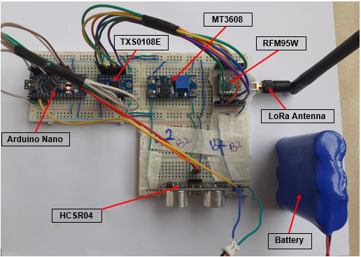
Figure 1: Breadboard layout of Project Muringato sensor node
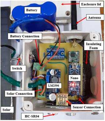
Figure 2: Deployment Ready Project Muringato Sensor Node
Below are brief descriptions of the components used.
Arduino Nano
An Arduino Nano is a small, complete (can be programmed independently) and light microcontroller board based on the ATmega328. Because of the qualities mentioned, the Nano is very suitable for prototyping. The power consumption of the Arduino Nano is also low which makes it fit for deployment. It has 8 analog pins and 22 digital pins which are used as interfaces with sensors and other devices. Apart from the USB port the Nano can also be powered via the 5V or VIN header pins. In the sensor node design (Figure 1 and 2), it is the main controlling unit in charge of data acquisition and transmission.
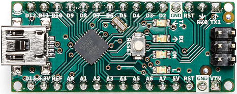
Arduino Nano
RFM95 LoRa Module
The RFM95W (868/915MHz) is a LoRa module. The RFM95 transceivers feature a LoRa long range modem that provides ultra-long range spread spectrum communication and high interference immunity whilst minimizing current consumption. On the sensor node, it is being utilized in data transmission.
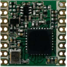
RFM95W LoRa Module
TXS0108E Bi-Directional Logic Level Converter Module
The TXS0108E bi-directional logic level converter module is a full-duplex 8-bit bi-directional converter/translator. The 20-pin converter module is capable of converting the logic level of 8-pins on the high side to 8-pins on the low side and vice versa. On the high side, the module can handled voltage values between 1.65 and 5.5V whereas on the low the module can handle 1.4-3.6V. Since the RFM95 module operates at a 3.3V logic level and the Arduino Nano operates at a 5V logic level, the TXS0108E is being used to facilitate the SPI communication between the two.
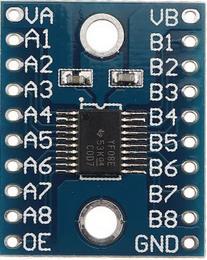
TXS0108E Bi-Directional Logic Level Converter Module
MT3608 Step-Up Adjustable DC-DC Switching Boost Converter
The MT3608 is a 2A DC-DC boost converter module capable of taking in input voltages as low as 2V and step up the output to as high as 28V. The Arduino Nano in the sensor node design is powered by a stable 5V output from the MT3608. The maximum voltage of the Lithium Ion battery used is 4.2V hence a boost module is needed to provide a constant 5V signal for all battery voltage levels. The MT3608 5V output is also used to power the ultrasonic sensor used in data acquisition. The blue rectangular component near the output pads is a variable resistor used in adjusting the output voltage to the required level.
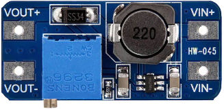
MT3608 Step-Up Adjustable DC-DC Switching Boost Converter
HC-SR04 Ultrasonic Sensor
The HC-SR04 is an ultrasonic sensor design which provides a 2cm-400cm non-contact measurement function with an accuracy of about 2mm. It has a working voltage and current of 5V and 15mA consecutively. To start ranging/measurement the sensor is supplied with a short 10μs pulse to its trigger terminal. The module then sends out an 8-cycle burst of ultrasound at 40 kHz. Lastly the module raises the echo of the 8-cycle burst coming in from as a reflection from an obstacle on its echo terminal. The distance is calculated using the time interval between the sending trigger signals and receiving echo signal. The microcontroller controls the HC-SR04 using the HC-SR04 library. Digital pins on microcontrollers can have two states/modes: LOW or HIGH, LOW meaning the voltage signal at that pin is 0 and HIGH meaning the voltage level at the pin is 5V or 3.3V depending on the logic level of the MCU (Arduino Nano: LOW=0V HIGH=5V). In most cases when READING the voltage level, a voltage below 0.8V is regarded as LOW and a voltage above 2V is HIGH. Before the utilization of the digital pins on Arduino, configuration of the mode is needed. A digital pin can either be in INPUT mode or OUTPUT mode. In INPUT mode the pin can be used to read data hence digitalREAD() but in OUTPUT mode the pin can be used to write data hence digitalWRITE().
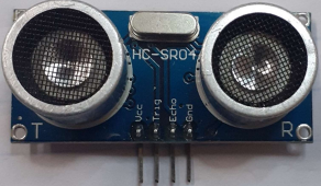
HC-SR04 Ultrasonic Sensor
When operating the HC-SR04 with an Arduino Nano, the trigger pin is first cleared and then it is set to HIGH to produce the short 10μs pulse. The echo pin is read at a high state with the PulseIn() function. The PulseIn() function reads the travel time of the echo pulse and puts the result into the variable = duration. The value of the PulseIn() function is HIGH, hence it will wait for the ECHO pin to go from LOW to HIGH level to start the timing and then wait for the pin to go LOW to stop the timing. The output of the PulseIn() function is given in microseconds and then used in distance/proximity calculation.
LM2596 DC-DC Buck Converter Step-down Power Module
The LM2596 is a power module used to step-down DC voltage. Its input voltage rating is +4 to 40Vdc whereas its output voltage rating is +1.23 to 35Vdc. The output current rating is 2A but can handled a maximum of 3A with a heat sink. The module is ideal for battery operated projects that require a regulated power supply. In the sensor node presented, the LM2596 is used to regulate the solar input voltage from a higher value to about 4.9V. The diode connected in series in turn drops the voltage to about 4.2V which is ideal for charging a 3.7V-nominal Lithium Ion battery. The diode also aids in avoiding back feeding from the connected battery.
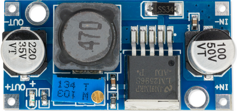
LM2596 DC-DC Buck Converter Step-down Power Module
Battery and Solar Panel
The battery used is a Lithium Ion ICR18650 6600mAh 3.7V battery. It is the main source of power for the sensor node. During deployment, the battery was also connected to a solar panel to facilitate charging.
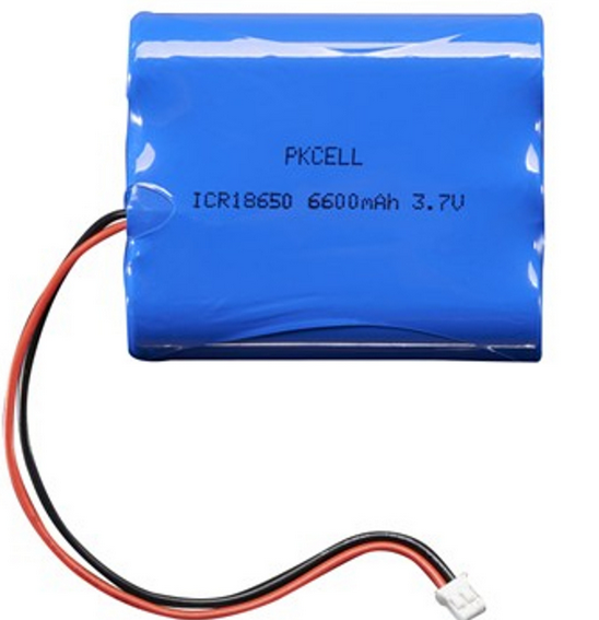
Lithium Ion Battery Pack - 3.7V 6600mAh
Antenna Connection
An antenna attachment to the antenna terminal of the RFM95 enables the transceiver to connect to the LoRa network. Since the antenna terminal of the RFM95 is not connected to a custom antenna socket, the terminal is connected to a copper track via the circuit board header pins, the track is then connected to a PCB antenna connector. The antenna connected to the socket is a 3dBi, 868MHz off-the-shelf LoRa antenna. On the breadboard design, the antenna attachment is facilitated by an etched circuit board that also aided in connecting the transceiver to the Arduino Nano.