Tutorial 2: Data Collection with LoRaWAN
Introduction
In this tutorial section, we will utilize the sensor node designs provided to collect distance data using the connected ultrasonic sensor. We will also record battery voltage data to track the battery voltage level. In Project Muringato, the battery voltage data aided in the scheduling of maintenance sessions by indicating the amount of power available for the sensor node. It also aided in discovering the effectiveness of the solar panel. The data collection exercise will include the following steps:
- Establishment of a LoRaWAN network to enable data transmission
- Introduction to The Things Network/Stack (TTN) as a network server and registration of the sensor nodes and network gateway on TTN
- Preparation of the sensor nodes and batteries
- Powering the sensor nodes
- Observation of data on the network server
Establishment of the LoRa Network
To establish the network, we will power up a programmed LoRa gateway/concentrator. We will also connect it to the internet and check its activity status on the things network. The gateway to be utilized is a Multitech Conduit LoRa gateway. The Conduit® is the industry's most configurable, manageable, and scalable LoRa® gateway for industrial IoT applications. Network connectivity choices to your preferred data management platform include carrier approved 4G-LTE, 3G and Ethernet. The Conduit LoRa gateway also includes a LoRaWAN® mCard capable of supporting thousands of LoRaWAN certified end nodes. Figure 1 shows the Multitech Conduit Gateway.
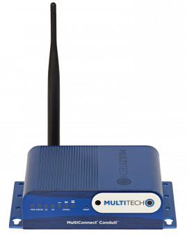
Figure 1: Multitech Conduit Gateway
Introduction to The Things Network (TTN)
An IoT (Internet of Things) system can be broadly divided into 3 main layers. The first layer is the perception layer which includes sensors and actuators involved in data collection. The second layer is the network layer which is responsible for communication between devices in the system. The network layer includes elements such as gateways and network servers. The last layer is the application layer, where an end user gets to interact with data output.
The network server under the network layer is a crucial component in a deployment scenario. The network server is a central element and is in charge of management of gateways, the authorization of end nodes and the exchange of data (uplink and downlink) between the sensor node and the user application.
The Things Network is a free LoRaWAN network server that is open to all. It has popularized the LoRaWAN technology by offering free services to IoT enthusiasts especially during initial tests before professional deployments.
Registration of the Sensor Nodes on TTN for Data Collection
To register the sensor nodes provided on TTN we are going to follow the simple steps provided below:
- Creating a TTN account
- Creating a TTN application
- Sensor node registration
Creating a TTN Account
- On your preferred search engine (e.g. Google), search for The Things Network official
website by typing
The Things Networkon the search bar. The first search result you get isthethingsnetwork.org. - Click on the search result link and it will forward you to the TTN homepage shown in Figure 2. You can also click this link (here).
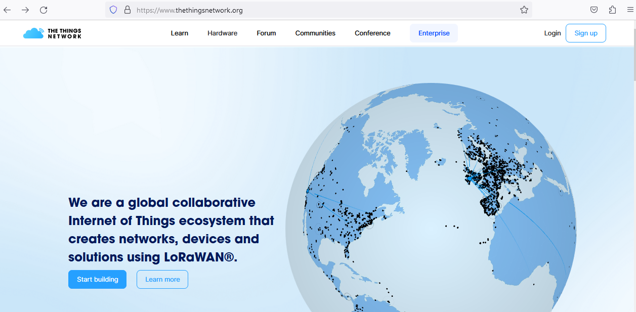
Figure 2: TTN homepage
- Click on the
Sign Upbutton (top right) to create a TTN account. - You will be presented with two choices as shown in Figure 3: click on
Join the Things Network.
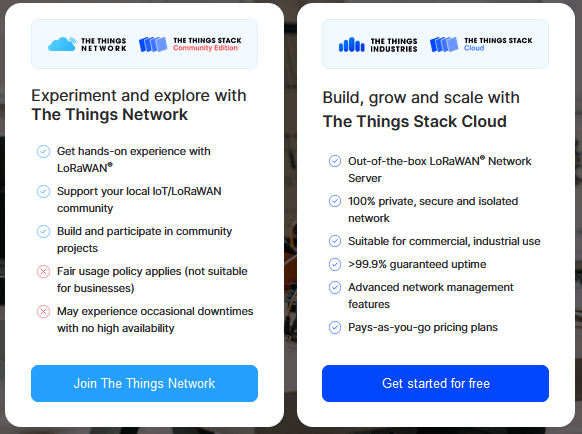
Figure 3: Sign up options
- You will be directed to the
The Things IDpage as shown on Figure 4. If you do not have an ID click onSign Up for Free.
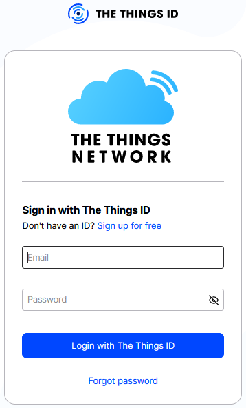
Figure 4: Signing up for a TTN ID
- After
Sign Up for Free, you will be directed to the registration page for you to access all the products on TTN. - Provide a
USERNAME,VALID EMAIL,PASSWORD, and also agree to theTerms and Conditions and Policiesby checking the box. - Click on
Sign up to The Things ID. - After sign up you will be notified your account has been created successfully as shown on Figure 5.
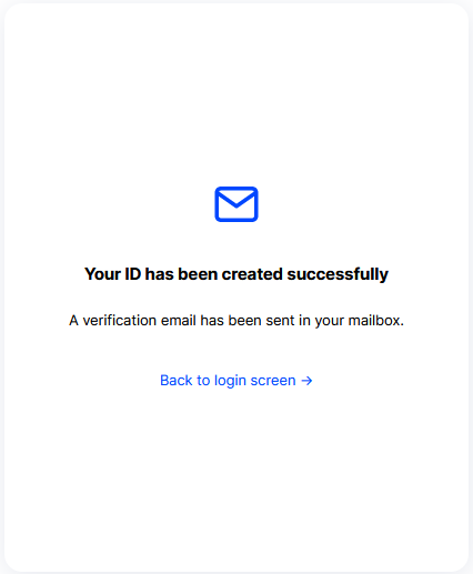
Figure 5: TTN account created successfully
- Before clicking on
Back to Login Screento log into your TTN account, log into your Gmail account and activate the TTN account you have just created using the no-reply email sent to you by TTN. - To login, on the login page provide the account email and the TTN password you created.
- After a successful login, you will be directed to the console terminal as shown on Figure 6.
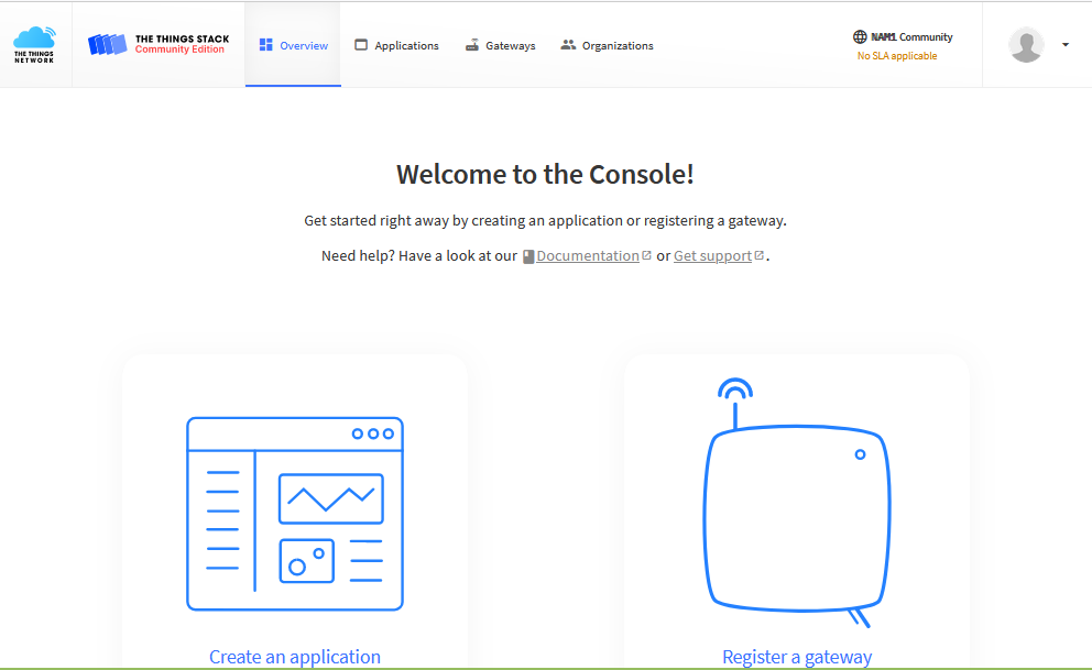
Figure 6: TTN console window after login
Creating a TTN Application
To register the sensor nodes on TTN we will start by creating an application. An application on
TTN houses the end nodes. To create the africon2023 application follow the short
procedure below.
- On the console page click on
create an application. - Since this is the first application you will create, you will be forwarded to
create application page. - Under creating an application, you will be prompted to provide an
application ID. Use the ID provided above (africon2023). The same can apply toapplication nameanddescription. - Click on
create application. - After creation you will be able to access the application as shown on Figure 7.
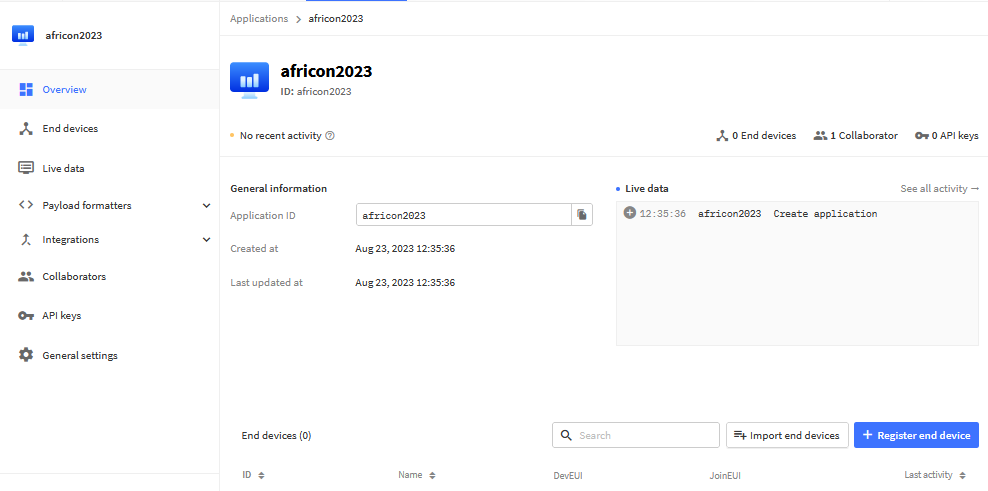
Figure 7: TTN application terminal
Sensor Node Registration on the Application - africon2023
To register an end device, follow the steps provided below.
- On the
africon-2023 application page, click onEnd Deviceson the left side bar. - Click on the
Register end deviceblue button on the far right. - You will be forwarded to the device registration page. Since the sensor node to be
registered is not commercially made or known, the registration will be done manually using
the following steps:
- Under
End device Type:- Input method:
enter end device manually - Frequency plan:
EUROPE 863-870MHz (SF9 for RX2 recommended) - LoRaWAN version:
LoRaWAN specification 1.0.2 - Regional Parameters Version:
RP001 Regional Parameters 1.0.2
- Input method:
- Click on
show advanced activation, LoRaWAN class and cluster settingand do the following:- Under activation mode: check
Activation by personalization (ABP) - Under additional LoRaWAN class capabilities:
None (Class A only) – default - Network defaults: check
use network's default MAC settings – default - Cluster settings: Do not check
skip registration on Join server – default
- Under activation mode: check
- Under
Provisioning Information:- Generate:
DevEUI - Generate:
Device Address - Generate:
AppSkey - Generate:
NwkSKey - Give the device an
End-Device ID(africon-water)
- Generate:
- Under
After registration:- check
View registered end device
- check
- Under
- Figure 8 shows the registered device terminal.
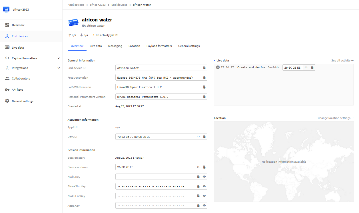
Figure 8: Registered device terminal
- On the registered device terminal, there are three main sections: General Information, Activation Information and Session Information. The keys under Session Information will be used in programming the sensor node. [Device address, NwkSKey, AppSKey].
- Further device settings:
- On the end-devices navigation bar, click on
General Settings - Collapse the
Basic Layer - Under
Network layer: LoRaWAN network-layer settings, behavior and session - Click on the
Advanced MAC Settings panel - Check the
reset frame countersbox - Save and exit
- On the end-devices navigation bar, click on
- Payload Formatter:
- Payload formatters allow you to process data going to and from end devices. This is
useful for converting binary payloads to human readable fields, or for doing any
other kind of data conversion on uplinks and downlinks. In this tutorial we will
utilize the CayenneLLP formatter. To activate it, follow the following steps:
- On the end-devices page navigation bar, click on
Payload Formatters. - Under uplink, in the
formatter typedrop down, selectCayenneLLPand save the changes.
- On the end-devices page navigation bar, click on
- Payload formatters allow you to process data going to and from end devices. This is
useful for converting binary payloads to human readable fields, or for doing any
other kind of data conversion on uplinks and downlinks. In this tutorial we will
utilize the CayenneLLP formatter. To activate it, follow the following steps:
- Getting ready for the data:
- Navigate back to the
overview page
- Navigate back to the
Uploading the Firmware onto the Arduino Nano
Requirements:
- A Laptop computer running the Arduino IDE (Arduino Nano IDE Download Link)
- Arduino Nano hardware Drivers
- Crucial Arduino LoRaWAN libraries
- Arduino Nano connection cable – to be provided
- Arduino Nano – dismount it gently from the sensor node designs provided
Files to be downloaded:
- Download the Arduino Nano hardware Drivers and the Arduino LoRaWAN libraries using this library link (Arduino Driver and Libraries Download Link)
- Unzip the file in an easy-to-locate folder such as the Desktop
- The sensor node firmware is located in the
arduino_codefolder
Firmware upload procedure:
- Install the Arduino IDE by running the installer (Arduino Nano IDE Download Link)
- Launch the IDE by searching it on your computer application list and clicking on it. Figure 9 shows the Arduino IDE interface.
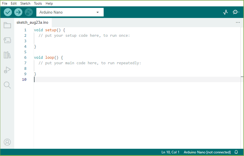
Figure 9: Arduino IDE interface
- To access the firmware on the Arduino IDE, click on
filethenOpen(Figure 9). Navigate to the downloaded unzipped file and click on the firmware under thearduino_codefolder. - To install the needed Arduino Nano drivers navigate to
arduino-libraries. Install theCH341SERand theCDM21228underarduino_hardware_drivers. - After driver installation, connect the Arduino Nano to the computer using the USB cable. On
the Arduino IDE, Click on
Tools(shown on Figure 9). UnderboardsselectArduino Nanoand underportselect the activated port. - After device selection, we have to add the LoRa arduino libraries. On the Arduino IDE
platform shown on Figure 9, click on
sketch–included library–Add .ZIP library. You will be prompted to add the zip libraries needed. Navigate to thearduino-libraries folderand select the zip libraries underLoRa-arduino-librariesand add. Repeat this procedure for all the libraries. - Before compiling the firmware, we need to add the "session keys" from TTN to the firmware as shown on Figure 10. Access the "registered end device terminal" shown on Figure 8. Under "Session information" copy the "device address" and paste it on the slot shown on line 23 of the firmware. Also copy the "network session key" and paste it on the slot provided on line 17 of the firmware. Do the same for "application session key" on line 20.
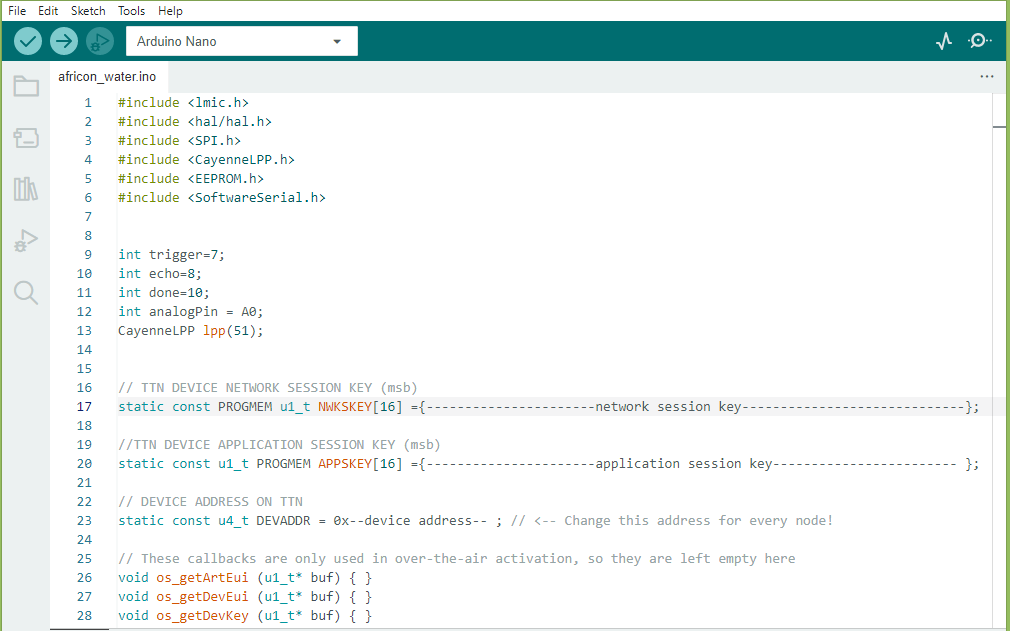
Figure 10: TTN Session keys
- After switching out the keys, click on
sketchand thenuploadon the Arduino IDE to upload the firmware on the Arduino Nano. - After the firmware upload is done, disconnect the Nanos from the computer and mount them back onto the sensor node slots.
- To power the breadboard layouts, connect the batteries as shown on Figure 11.
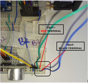
Figure 11: Battery connection to the breadboard
- The deployment ready designs are powered by connecting the battery directly to the battery socket.
- Once the device is powered, observe the device activity on TTN and also check the
live data terminalfor the data as shown on Figure 12.analog_in_1represents the distance measured by the ultrasonic sensor whereasanalog_in_2represents the battery voltage.
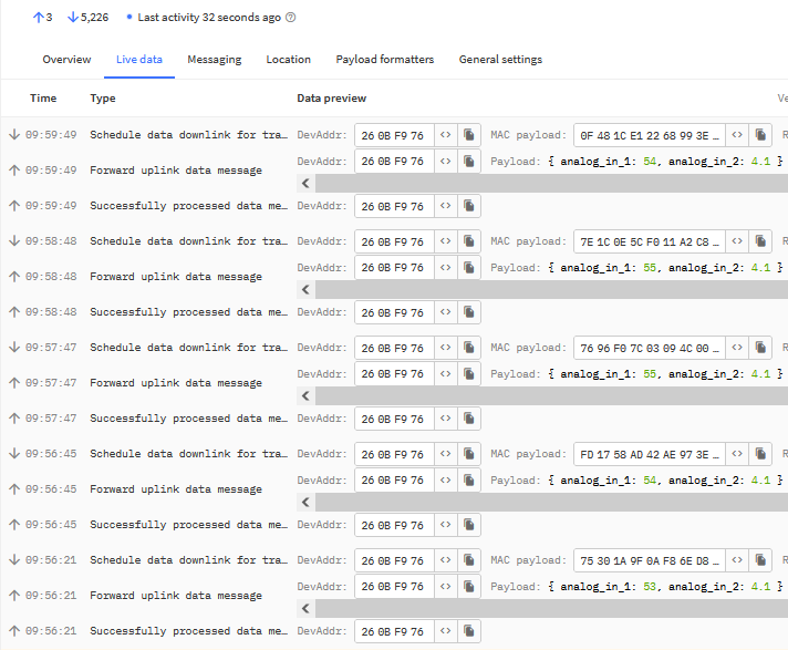
Figure 12: Data on TTN